The "Baron Munchausen" opamp
How it all started
Hello friends, today I want to tell you a story about a dual operational amplifier which self-generates it’s negative supply rail. But before we get to it, we must understand how me and my friend got there and why we needed it in the first place.
So the whole plot happened about 4 years ago, during my freshman’s year at the university, studying electronics. I had an internship in a company near uni campus where me and my friend stayed after work hours to mess around with self designed circuits.
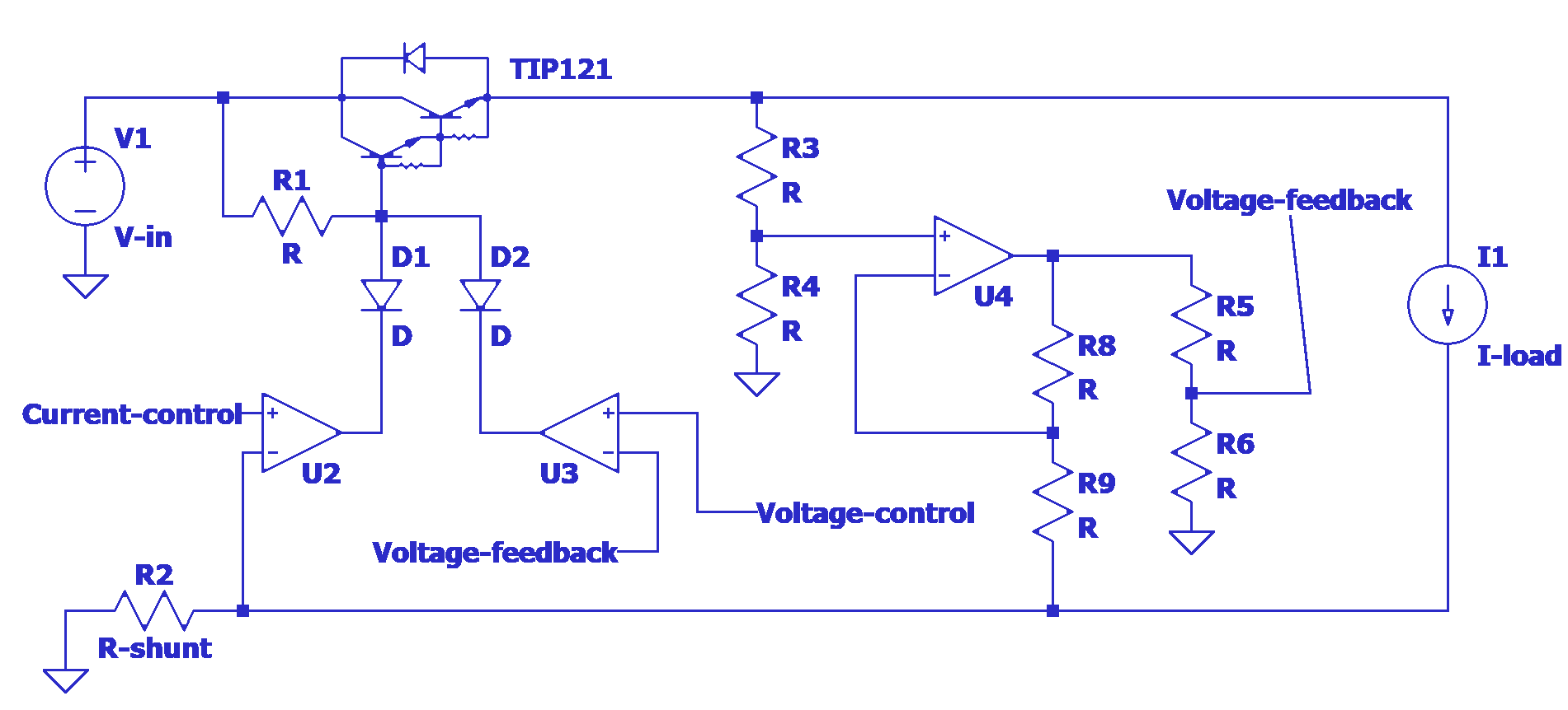
One day, we were checking quite the intriguing linear power supply regulator:

The interesting part is the active compensation of the voltage drop over R2 (R-shunt) so it can be placed in the low side. We just have to ensure that the proportion R3/R4 is the same as R9/R8. Notice how one of the proportions is reversed.
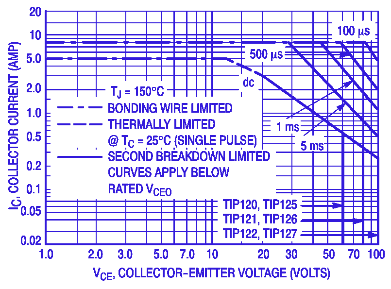
Now let’s bring the circuit to life or in other words let’s specify component values. The main Darlington pair (TIP121) should be able to handle 2A at 25V according to the datasheet:

So we may specify our PSU to be able to supply 0-20V and 0-2A (We won’t worry how to dissipate 40W for now). The shunt resistor (R2) will be 500mΩ 2W which means that the current control signal will be in the range 0-1V. The required input voltage will be 24V, which leaves us with budget of 3V collector-emitter drop on the TIP121 in the worst case (20V for the output, 1V for the shunt and 3V to spare). The choice for opamps is endless. They need to be able to handle more than 24V differential supply. Me and my friend did not have much choice back then however. We had to use LM358. R3, R4, R8 and R9 will all be 10kΩ precision resistors. The 10kΩ value is chosen according to the opamp’s input offset current. In the LM358’s worst case it is 30nA, which means that the opamp’s output may have error of ±150µV (the equivalent impedance of the dividers will be 5kΩ). And in the worst case we will have 1mA parasitic current draw per divider. R5 will be 18kΩ and R6 will be 2kΩ. That makes the voltage control range to be 0-1V. D1 and D2 should be fast signal diodes - 1N4148 will do. R1 will be 5kΩ and we may need to replace it with JFET configured as current source.
Now that all the components are specified and we have our output parameters, we may conclude that the circuit is ready, but we will be wrong. In fact that circuit with these components is guaranteed 100% to be unstable and oscillate. To mitigate the oscillations we have to remember some key principles in control theory and reduce the control loop gain at high frequencies. Simply we should not try to control our main power element (TIP121) faster than it’s ability to respond to our commands. To do that we have to slow down our opamps and the easiest way to do that is to connect small capacitor between the output and the inverting input (of the opamps). How small you may ask and I will respond that the best way is to build the circuit and figure that out experimentally. Simulating the circuit is an option too, but do not bet your life on the simulated results.
The problem
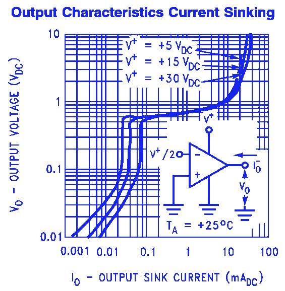
Now that we have specified the components and stabilized the control loop we should have a nice functional linear PSU right? Well, almost. When the PSU is in current limiting mode, the opamp U4 should output 0V. According to the datasheet form LM358, it should be able to swing it’s output to ground, but when we get to the details, we can find this diagram:

And now we can figure that if we are current limiting at 2A, the shunt voltage will be 1V and the opamp have to sink 1V / 20kΩ = 50µA which means that the opamp sometimes won’t be able to swing under 200mV depending on the input voltage. This unfortunately means that our circuit is still not functional unless we add negative supply rail. What a bummer…
The solution
In order to build the PSU, we had to choose real components. For the opamps we chose a jelly-bean part - LM358. However as you may know, LM358 has two opamps per package, so we ended up with one free. And here comes the realisation - what if we could use that one free opamp to build a charge pump? …